
Exploring the 3GPP UPF – User Plane Function
The User Plane Function, or UPF, is a key component of the 5G network as it enables low latency and high throughput. The UPF represents the data plane evolution of a Control and User Plane Separation (CUPS) strategy, which decouples control and user plane functions to allow packet processing and traffic aggregation to be performed in the core or closer to the edge of the network. In turn, this helps to increase bandwidth efficiencies and reduce network traffic.
User Plane Function (UPF) in the 5G SBA
In an LTE core network, two of the most important nodes are the Serving Gateway (SGW) and the Packet Data Network Gateway (PGW), each of which has a control plane component and a user plane component. For several reasons, most implementations opted to keep them separate, so for them to work together, many implementations required a proprietary interface between the two planes.
However, starting with Release 14, the 3GPP recognised the growing practical importance of the separation of control and user plane components in future 5G networks, for multiple reasons:
- The User Plane can then be located close to RAN to reduce the latency when forwarding data to the relevant processing resources – and thus to unlock new applications for numerous B2B cases, among others.
- The User Plane capacity can be increased by adding more nodes without a need to increase Control Plane nodes.
- It enables the independent location and scalability of the User Plane and Data Plane.
- Enables individual feature evolution and upgrade of the User Plane and Data Plane.
- The Control Plane can be located in the cloud – meaning that the User Plane is controlled in a Software-Defined Networking (SDN) fashion by the Control Plane.
To deliver these benefits, and to avoid vendor lock-in, the 3GPP defined a formal protocol between the Control Plane and User Plane called the Packet Flow Control Protocol (PFCP) – as specified in 3GPP TS 29.244.
The User Plane component which implements the PFCP and does the east-west shunting of data is the UPF in 5G. Here, the interface between the Control Plane – which in 5G is the Session Management Function (SMF) – and the UPF is the N4 interface.
Figure 1 – 3GPP 5G Standalone service-based architecture (SBA)
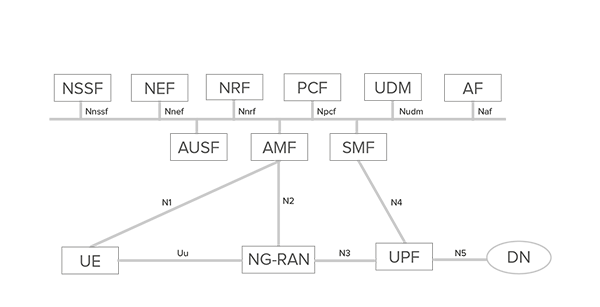
Source: Emblasoft
Functions of the UPF
Defined in technical specification 3GPP TS 23.501 (Release 15 onwards) the UPF includes the following functionality (some or all of the UPF functionalities may be supported in a single instance of a UPF):
- Anchor point for Intra-/Inter-RAT mobility (when applicable).
- Allocation of UE IP address/prefix (if supported) in response to SMF request.
- External PDU Session point of interconnect to Data Network.
- Packet routing and forwarding (e.g., support of Uplink classifier to route traffic flows to an instance of a data network, support of Branching point to support multi-homed PDU Session, support of traffic forwarding within a 5G VN group (UPF local switching, via N6, via N19)).
- Packet inspection (e.g., Application detection based on service data flow template and the optional PFDs received from the SMF in addition).
- User Plane part of policy rule enforcement, e.g., Gating, Redirection, Traffic steering.
- Lawful intercept (UP collection).
- Traffic usage reporting.
- QoS handling for user plane, e.g., UL/DL rate enforcement, Reflective QoS marking in DL.
- Uplink Traffic verification (SDF to QoS Flow mapping).
- Transport level packet marking in the uplink and downlink.
- Downlink packet buffering and downlink data notification triggering.
- Sending and forwarding of one or more "end markers" to the source NG-RAN node.
- Packet duplication in downlink direction and elimination in uplink direction in GTP-U layer.
Hence, the UPF represents the data plane evolution of a Control and User Plane Separation (CUPS) strategy, first introduced as an extension to existing Evolved Packet Cores (EPCs) as defined in the 3GPP Release 14 specifications.
CUPS decouples Packet Gateway (PGW) control and user plane functions, enabling the data forwarding component (PGW-U) to be decentralised. This allows packet processing and traffic aggregation to be performed closer to the network edge, increasing bandwidth efficiencies while reducing network.
Key advantages of a decoupled UPF
The decoupling of the UPF – responsible for packet detection, data forwarding, usage reporting, and so on – from the SMF, which controls user sessions in the UPF, is therefore one of the key advantages of the 5G core infrastructure system architecture over previous network technologies.
This decoupling essentially enables new levels of performance for end-user data applications by enhancing packet processing and traffic aggregation capabilities for high-performance, mission-critical 5G applications anywhere in the network – at the core or at the edge. The ability to process at the network edge increases bandwidth efficiencies, enables low-latency applications, and reduces core network traffic.
To meet 5G’s requirements for granular capacity or application-driven, instantiation and elastic scaling, the UPF must be implemented as a pure cloud-native network function using today’s microservices methodologies.
Delivering a cloud-native UPF on shared resources demands solving complex real-time data processing problems and providing a high degree of flexibility. UPF instantiation must also be highly automated and orchestrated, which requires tight integration with cloud orchestration systems, such as Kubernetes.
Figure 2: Four distinct reference points for the UPF
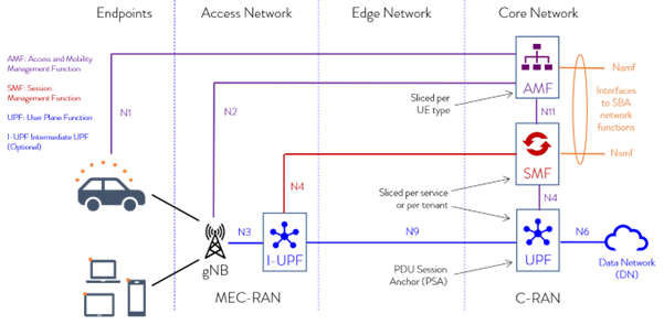
As shown in Figure 2, the UPF has four distinct reference points:
- N3: The interface between the RAN (gNB) and the (initial) UPF.
- N9: The interface between two UPFs (i.e. the Intermediate I-UPF and the UPF Session Anchor).
- N6: The interface between the Data Network (DN) and the UPF.
- N4: The interface between the Session Management Function (SMF) and the UPF.
N3 Interface
The 5G N3 interface performs the role of conveying user data from the RAN to the User Plane Function, making it possible to create both low- and high-latency services. It replaces the S1-U interface from the 4G EPC and is key for supporting the new CUPS architecture, with distributed user data processing. Testing and validation of these interfaces is essential, but a challenge.
N9 Interface
A special feature of the 5G Core UPF is that two UPFs can be deployed in series and connected via an interface referred to as N9. There are three main use cases for this:
- Network-wide mobility – To provide full mobility with a stable IP anchor across the full network, there may be a need to connect two UPFs depending on the operator network configuration.
- Break-out of selected data flows – A new function in the 5GC is the ability to apply classification and traffic management in the UPF to selectively send IP packets to different IP interfaces, for example, to terminate some traffic at, or close to, the edge to ensure low data latency or prevent sensitive data from being intercepted in more central areas of the network. This requires two UPFs connected in series.
- Roaming with home routing – 5G roaming for voice is referred to as N9 home routing (N9HR) and is needed for smartphones.
N6 Interface
In 4G networks, the SGi interface is defined by the 3GPP as the interface between the EPC and the Public IP network. Importantly, traffic through the interface can be identified by user IP, making user and service differentiation a reality. As such, the SGi interface can be perceived as a service gateway, and is a key enabler for new services, particularly when combined with functions such as deep packet inspection and policy-based service selection.
The N6 interface plays the same role in the 5G network, providing connectivity between the UPF and any other external (or internal) networks or service platforms, such as the Internet, the public cloud or private clouds.
N4 interface
The N4 interface, or reference point, connects the User Plane Function (UPF) and the 5G Session Management Function (SMF). It plays a fundamental role in enabling the 5G network vision. That’s why it’s essential to simulate and test the behaviour and characteristics of ‘real world’ N4 traffic scenarios produced by the SMF within both the core network and at the edge.
How can Emblasoft help?
The UPF plays a key role in the 5G network to realise the promises of low latency and high throughput. To ensure that it delivers and meets performance demands for all services, effective, continuous testing is required – in an automated environment.
A UPF testing solution must be able to provide node-isolation by emulating the complete 5G network, including the generation of massive traffic load, and capable of running a wide range of test cases and scenarios, and modelling real traffic under different conditions.
How can this be done?
Emblasoft’s test solutions can continuously verify UPF functions and performance. Our range of 5G test solutions enable independent verification and load testing of the distributed UPFs required to support edge processing for IoT (and other) applications and services. In this environment, it will be essential that the UPF scales and delivers. They can emulate key 5G nodes, including:
- 5G RAN function – gNodeB / gNB
- 5G SBA core
- 5G data network via N6
Our solutions enable end-to-end test cases to be run in multi-vendor environments, depending on requirements, providing:
- Individual node testing and assurance
Testing individual nodes and interfaces in isolation or in parallel to validate end-to-end functionality and performance.
- Validate CUPS and model traffic scenarios
Support distributed UPF deployments with CUPS, across multi-vendor networks and EDGE computing/offload
- Scale in live and staging networks
Simulate from 1 to millions of users, and deploy hundreds of live software agents for continuous, active monitoring
- Full 3GPP interface support
Model UPF, AMF, NRF, SMF, PCF and other nodes, with support for N1, N2, N3, N4, N6, N11 and more
Importantly, from both a business and operational perspective, Emblasoft’s solutions can be fully automated and are aligned with Operator DevOps release programmes and continuous innovation cycles.
This ensures that service iterations can be tested effectively and automatically, supporting agile adoption of the UPF, and reflecting dynamic changes to support any of the numerous use cases that will be delivered by operators seeking to capitalise on new 5G IoT opportunities.
To find out how Emblasoft’s powerful testing solutions can validate and optimise UPF nodes end-to-end, within a DevOps environment, why not download our case study, focused on the verification of UPF nodes in 5G standalone networks, or get in touch today?